


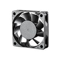
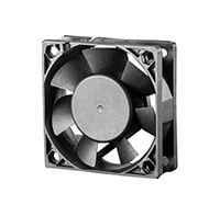
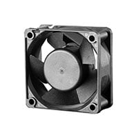
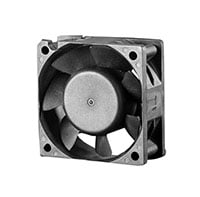
Today’s high technology industries require cooling products that have low power consumption and reduce high heat generation. Brushless DC Axial fans with Intelligent Motion Controls are made for applications that require high performance cooling and protection from harsh weather conditions in outdoor and extreme environments.
Rugged Design For Effective Cooling
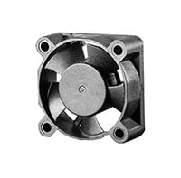
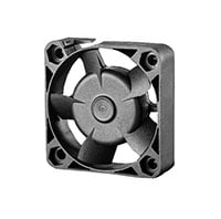
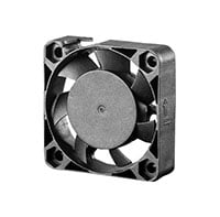
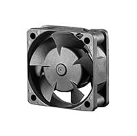
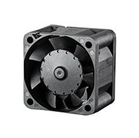
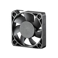
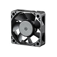
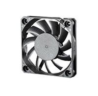
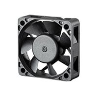
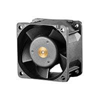
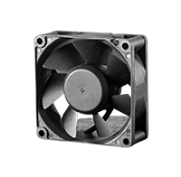
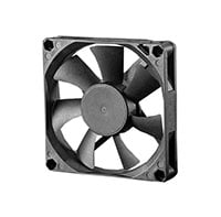
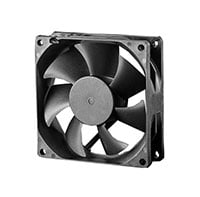
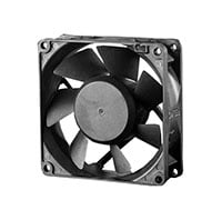
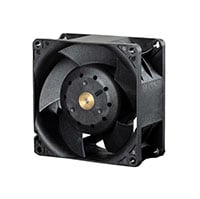
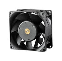
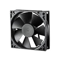
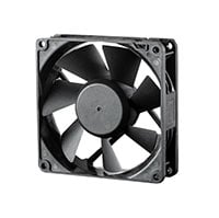
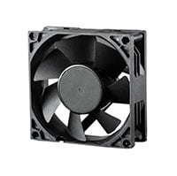
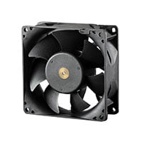
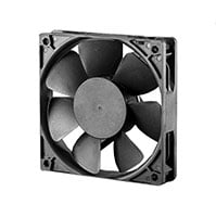
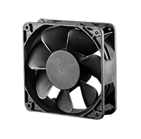
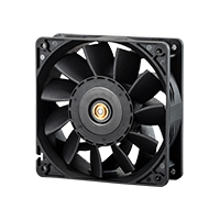
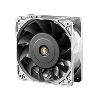
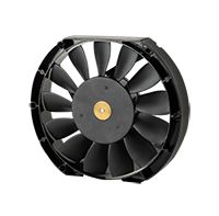
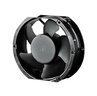
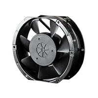
The Intelligent Motion series Brushless DC Axial fans ensure effective cooling via innovative multi-blade impeller designs that improve airflow performance. They also include IP51, IP54, IP56, or IP67 levels of dust and moisture protection for applications that are used in moderate to very harsh environmental conditions.
Intelligent Motion Control
The Intelligent Motion series Brushless DC Axial fans include full-wave in-board circuit designs with multiple features that create air movement “intelligence”. By using controls that are programmable, voltage fluctuations from power supplies are reduced, protection is enhanced, and optimum performance is ensured.
Intelligent Motion Controls improve operating efficiency and are ideal for green applications. Additional benefits include the following:
- Improved system performance
- Improved system reliability and life expectancy
- Fully programmable features enable greater control and functionality
- Multi-alarm connections to run many fans at once
Intelligent Motion Controls include tachometer, rotation detection, life detection, pulse width modulation, automatic temperature control, current limit control, constant speed control, multiple alarm connections, and others. Various controls can also be programmed for custom output.
DC Fan Series Specifications Guide
| Fan Series |
Size mm (in) |
Voltage | Airflow | ||||
|---|---|---|---|---|---|---|---|
| Length | Width | Height | V | CFM | m3/min | ||
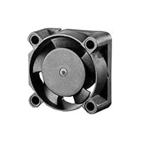 |
2510-5 | 25 (0.98) | 25 (0.98) | 10 (0.39) | 5,12 | 1.4~2.9 | 0.04~0.08 |
 |
3010-5 | 30 (1.18) | 30 (1.18) | 10 (0.39) | 5,12 | 3~4 | 0.07~0.12 |
 |
4010-5 | 40 (1.57) | 40 (1.57) | 10 (0.39) | 5,12,24 | 4~9 | 0.12~0.25 |
 |
4010-7 | 40 (1.57) | 40 (1.57) | 10 (0.39) | 5,12,24 | 4~8 | 0.11~0.23 |
 |
4015-5 | 40 (1.57) | 40 (1.57) | 15 (0.59) | 5,12,24 | 6~14 | 0.18~0.39 |
 |
4020-5 | 40 (1.57) | 40 (1.57) | 20 (0.79) | 5,12,24 | 5~19 | 0.14~0.52 |
 |
4020-7 | 40 (1.57) | 40 (1.57) | 20 (0.79) | 5,12,24 | 5~11 | 0.14~0.31 |
 |
4028-5 | 40 (1.57) | 40 (1.57) | 28 (1.10) | 12,24 | 12~27 | 0.35~0.77 |
 |
4028-7 | 40 (1.57) | 40 (1.57) | 28 (1.10) | 12,24 | 8~25 | 0.23~0.70 |
 |
5010-7 | 50 (1.97) | 50 (1.97) | 10 (0.39) | 5,12,24 | 9~18 | 0.26~0.51 |
 |
5015-7 | 50 (1.97) | 50 (1.97) | 15 (0.59) | 5,12,24 | 12~23 | 0.34~0.65 |
 |
6010-11 | 60 (2.36) | 60 (2.36) | 10 (0.39) | 5,12,24 | 16~20 | 0.44~0.56 |
 |
6015-9 | 60 (2.36) | 60 (2.36) | 15 (0.59) | 5,12,24,48 | 14~23 | 0.40~0.66 |
 |
6020-7 | 60 (2.36) | 60 (2.36) | 20 (0.79) | 5,12,24,48 | 14~33 | 0.39~0.94 |
 |
6025-5 | 60 (2.36) | 60 (2.36) | 25 (0.98) | 5,12,24,48 | 18~38 | 0.50~1.08 |
 |
6025-7 | 60 (2.36) | 60 (2.36) | 25 (0.98) | 5,12,24,48 | 15~29 | 0.44~0.83 |
 |
6026-7 | 60 (2.36) | 60 (2.36) | 25 (0.98) | 12,24,48 | 27~47 | 0.78~1.34 |
 |
6038-5 | 60 (2.36) | 60 (2.36) | 38 (1.50) | 12,24,48 | 39~67 | 1.10~1.89 |
 |
7025-7 | 70 (2.76) | 70 (2.76) | 25 (0.98) | 5,12,24,48 | 24~44 | 0.68~1.25 |
 |
8015-7 | 80 (3.15) | 80 (3.15) | 15 (0.59) | 5,12,24,48 | 26~44 | 0.74~1.23 |
 |
8025-7 | 80 (3.15) | 80 (3.15) | 25 (0.98) | 5,12,24,48 | 29~58 | 0.82~1.64 |
 |
8026-7 | 80 (3.15) | 80 (3.15) | 25 (0.98) | 5,12,24,48 | 32~72 | 0.89~2.03 |
 |
8038-5 | 80 (3.15) | 80 (3.15) | 38 (1.50) | 5,12,24,48 | 59~136 | 1.67~3.85 |
 |
8038-7 | 80 (3.15) | 80 (3.15) | 38 (1.50) | 5,12,24,48 | 56~141 | 1.59~3.98 |
 |
9225-7 | 92 (3.62) | 92 (3.62) | 25 (0.98) | 5,12,24,48 | 41~82 | 1.16~2.32 |
 |
9226-7 | 92 (3.62) | 92 (3.62) | 25 (0.98) | 5,12,24,48 | 49~107 | 1.37~3.02 |
 |
9232-7 | 92 (3.62) | 92 (3.62) | 32 (1.26) | 5,12,24,48 | 52~87 | 1.47~2.47 |
 |
9238-7 | 92 (3.62) | 92 (3.62) | 38 (1.50) | 12,24,48 | 72~164 | 2.03~4.63 |
 |
1225-7 | 120 (4.72) | 120 (4.72) | 25 (0.98) | 5,12,24,48 | 78~177 | 2.21~5.00 |
 |
1232-5 | 120 (4.72) | 120 (4.72) | 32 (1.26) | 12,24,48 | 107~240 | 3.04~6.79 |
 |
1232-7 | 120 (4.72) | 120 (4.72) | 32 (1.26) | 5,12,24,48 | 81~179 | 2.29~5.06 |
 |
1238-5 | 120 (4.72) | 120 (4.72) | 38 (1.50) | 12,24,48 | 190~237 | 5.39~6.71 |
 |
1238-7 | 120 (4.72) | 120 (4.72) | 38 (1.50) | 5,12,24,48 | 104~232 | 2.96~6.56 |
 |
1238-11 PL | 120 (4.72) | 120 (4.72) | 38 (1.50) | 12,24,48 | 142~257 | 4.02~7.29 |
 |
1238-11 AL | 120 (4.72) | 120 (4.72) | 38 (1.50) | 12,24,48 | 166~278 | 4.69~7.86 |
 |
1725-13 | 172 (6.77) | 150 (5.91) | 25 (0.98) | 12,24,48 | 163~272 | 4.62~7.71 |
 |
1751-5 | 172 (6.77) | 150 (5.91) | 51 (2.00) | 12,24,48 | 180~374 | 5.10~10.60 |
 |
1751-7 | 172 (6.77) | 150 (5.91) | 51 (2.00) | 12,24,48 | 194~323 | 5.49~9.15 |
Intelligent Motion Controls
 Intelligent Motion Controls are additional features that can be added to select DC fans to help improve performance and efficiency. Various controls include Tachometer, Rotation Detection, PWM speed control, Life Detection, and others.
This guide serves to educate end users on not only the engineering “how” of DC Fan intelligent motion controls, but also the “why,” including operating
efficiency suitable for green applications, as well as improved system
performance, reliability and life expectancy.
DC Fans Selection Guide
The following points should be considered when selecting a cooling fan:
- Determine the amount of heat generated inside the equipment.
- From the equipment manufacturer's data, find the maximum permissible equipment temperature.
- Calculate the air volume necessary from the equation.
- Select the fan from the performance curves shown inthe fan specification sheets. The volume of airflow required to cool the equipment can be determined if the internal heat dissipation and the total allowable temperature rise are known.
The basic heat transfer equation is:
Q = Cp x W x T
Where:
Q = Amount of heat transferred
Cp = Specific heat of air
T = Temperature rise within the cabinet
W = Mass flow = CFM x D
(Where: D = Air Density and CFM is cubic feet / min)
By substitution, we obtain:
Air Flow in CFM = Q / Cp x D x T
Then, we get the following equations:
Air Flow in CFM = 3.16 x P / Tf = 1.76 x P / Tc
Air Flow in m3/min = 0.09 x P / Tf = 0.05 x P / Tc
P : Internal power dissipation in watts
Tf : Allowable temperature rise in °F
Tc : Allowable temperature rise in °C
T : T2 - T1
T1: Incoming airflow temperature
T2: Outgoing airflow temperature
T1: Incoming airflow temperature
T2: Outgoing airflow temperature
1 m3 / min = 35.325 CFM (Cubic Feet / min)
Cooling of Heat Generating Equipment
Example 1: If internal power dissipation is 1500W and T is 50°F
Air Flow in CFM = 3.16 x 1500 / 50 = 94.8 CFM (or 2.68 m3/min
Example 2: If internal power dissipation is 1000W and T is 20°C
Air Flow in CFM = 0.05 x 1000 / 20 = 2.5 m3/min (or 88.3 CFM)